Telephone hybrid circuit is the circuit which is designed
for converting 2-wire interface to 4-wire interface and is one of the basic building blocks
of the telephone system.
Telephone hybrid is the circuit which separates the transmitted and received audio which are sent both
at the same wire pair in 2-wire normal telephone interface.

There are many different types of hybrid circuit in use.
Traditionally telephones have used combination of special transformer
and few additional components to keep incoming and outgoing signal separated from each other.
Nowadays this is done more or less electronically.

In telephone central end hybrid circuits are needed when must be done any amplification to the signal.
Traditionally the systems separate the incoming and outgoing signal,
then they are amplified separately and sent to other telephone central using separate wires
or otherwise separate communication channels.

The oldest models of those circuits have been built from one or two transformers
and some other balancing components to get best results.
The problem have been how to get good balance to the hybrid circuit,
said in other way how to separate incoming and outgoing signals as well as possible.

Nowadays everybody is avoiding bulky and expensive special transformers
and more and more electronics is used because it is cheaper.
Modern hybrid circuits consists only of one audio isolation transformer,
two operational amplifiers, resistors and some capacitors.

and the most modern approaches try to avoid that transformer altogether
by using active electronics circuits in telephone line side to do the job
and optocouplers to do the isolation where needed.


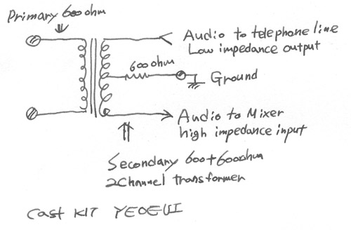
This first circuit is a traditional simple hybrid circuit which have been earlier successfully
used in many telephone circuit (for example modems).
The circuit works so that the 600 ohm resistor
in the center pin of the secondary is seen as 600 ohm impedance load in primary circuit.

The end of the secondary which is connected to low impedance audio output
(for example amplifier made for driving small speaker)
must be always connected to amplifier or ground to make the circuit work as expected.

The audio signal output from the circuit must be fed to high impedance (>10 kohm)
audio input to make sure that the operation of the circuit is not disturbed.

The circuit gives quite acceptable separation between incoming
and outgoing signals when all impedances are set correctly.
The 600 ohm impedance is kind of idealistic value and does not fully reflect the reality.
In real life the impedance of the telephone line or telephone is not exactly 600 ohm
and the transformer has it's losses. A 600 ohm resistor is anyway quite a good starting point.

If transmitted and received signals mix with each other,
you will have to fiddle with the balancing network.
For experiments I can suggest fitting 1 kohm variable resistor to the pace of 600 ohm resistor
for experimenting which impedance value gives the best results.

You may also want to try other type of line impedance simulation circuits
if you know what what matches your system better.
If the impedances presented by both the send and receive sides are the same
the hybrid circuit will work quite well.
You will find that the send and receive signals don't interfere with each other,
but both come and go from and to the line.

If you are thinking of connecting this circuit to telephone line or otherwise sending
DC current through the primary of the transformer remember
to use a transformer which can handle the DC without saturating
(telephone transformers made for "wet" circuits).

And remember that there are strict rules what the equipment you connect to telephone line
must meet and you are not allowed to connect anything not approved to public telephone system.
|