Operational amplifier based hybrid circuits
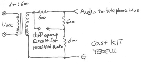
Modern modems use hybrid circuits built from operational amplifiers,
resistors and one 600:600 ohm isolation transformer.
With operational amplifier circuit the circuit can be made cheaper and performing better.


The source for audio signal which is transmitted to the telephone line
should be low impedance to ensure that the impedance matching to telephone line is correct.
For receiving audio a differential amplifier must be used to separate the incoming signal
form outgoing signal, but differential amplifier is very easy to implement using operational amplifiers.

The performance of the circuit can be made better by replacing the 600 ohm resistor
which is marked by * with some better model for the telephone line
seen through the isolation amplifier.
A better model provides better isolation between incoming and outgoing audio signals.

A quick note to mixing desk users:
professional mixing desks nowadays have differential inputs and low impedance outputs.
This makes it very easy to experiment with this type of circuit if you happen to own a good audio mixer.

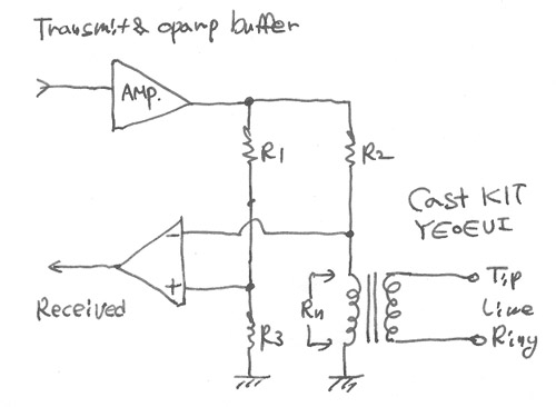
Here is the full operational amplifier based hybrid circuit diagram (theoretical circuit):


In the above diagram Rn = the telco network impedance as seen at the other side of the transformer.
This circuit is an example of an "active" hybrid. Essentially it is a balanced network.
If the ratio of Rl/R3 = R2/Rn, then you have infinite return loss - that is,
you should have none of your transmit signal appearing on your receive line
(when this happens, this signal is called side-tone).

Yet the receive signal from the "far-end" will appear on the receive line. In other words,
two signals can use the same two-wire interface, yet are seperable.
Not theat the resistors which define the amplification of the opamps are not drawn here,
so if you are plannign to build this circuit you will have to add them.

Unfortunately, telco line impedances can vary quite a bit,
so the ratio of R2/Rn rarely equals R1/R3 except in situations where the designer has tight control
over loop lengths and terminations.
Any imbalance in the balanced network creates sidetone - a small amount of the transmit signal
will appear on the receive line.
In typical situations the sidetone can be attenuated aroun 20-30 dB with a well designed hybrid circuit.

Another typical way to implement a hybrid circuit is to build an optoamplifier circuit which takes
the signal over the transformer coil and subtracts the transmitted signal from it.

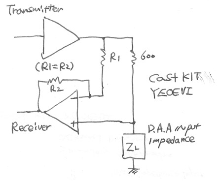
The following operational amplifier circuit does this:


The transformer in this circuit is 600:600 ohm telephone line transformer.
For best results you have to adapt the component values slightly to match the line impedance
and the transformer you are using.

That upper amplifier (the triangle with one input and output wire) is just a buffer amplifier
with amplification factor of one.
Signal from transmitter is connected to the positive input of opamp.
The negative input of that opamp is conected to the opamp output.
|
|
|
|
 번개알통 번개알통 |
|
|
그림은 감이 오는데 저거 부품은 또 어떻게 찾아야 하는지....에공.....드뎌 머리에 쥐 납니당~~~~
|
| 2006.08.19 - 23:33 |
| |
|
|
 철통 철통 |
|
|
한글로바도 어려운대,,영어루,,,암튼 스쳐 보고는가요,, 수고하세요^^,
|
| 2007.04.02 - 20:05 |
| |
|
|